A sensor keeps sending a plausible value while the actuator moves away from it. The primary controller stops responding. Two measurements disappear while the system is approaching its requested position. Control software must handle these conditions, yet ordinary bench tests can make them difficult to reproduce.
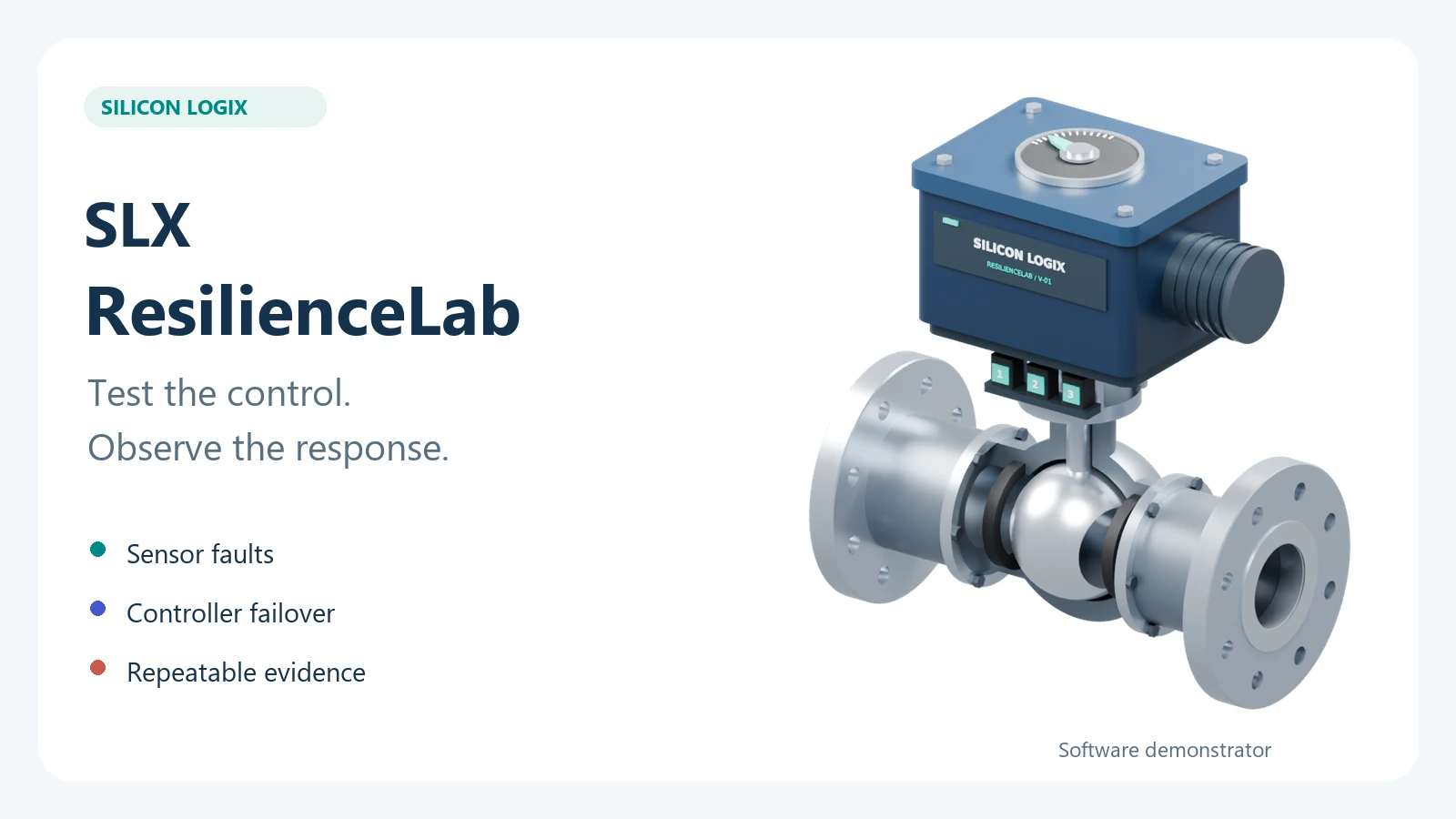
SLX ResilienceLab is Silicon LogiX's new desktop demonstrator for exploring these cases in an entirely software-based test bench. A virtual motorized valve, three position sensors and two C++ controllers let you observe the response, inject faults and retain the results. The project demonstrates how a dedicated test environment can be built around a product's control software.
For teams developing boards, firmware or machinery, the practical value is repeatability: recreate a critical condition, compare two control versions and discuss the response using recorded measurements, timings and events. Contact me to discuss a test bench for your product.
A virtual valve with decisions computed by the software
The operator requests an opening, such as 80%, and follows the valve's movement in normal and cutaway 3D views. The interface keeps requested opening, actual model position, three sensor readings and the control measurement separate. This makes it possible to see when a reading no longer represents the movement.
The primary and backup controllers execute real C++ code. They receive measurements and messages through a virtual transport and calculate the motor command. They cannot directly inspect the plant's actual position or the operator's fault settings: they must respond using received information. Heartbeats, commands and measurements travel through the transport, where delays and losses can be introduced.
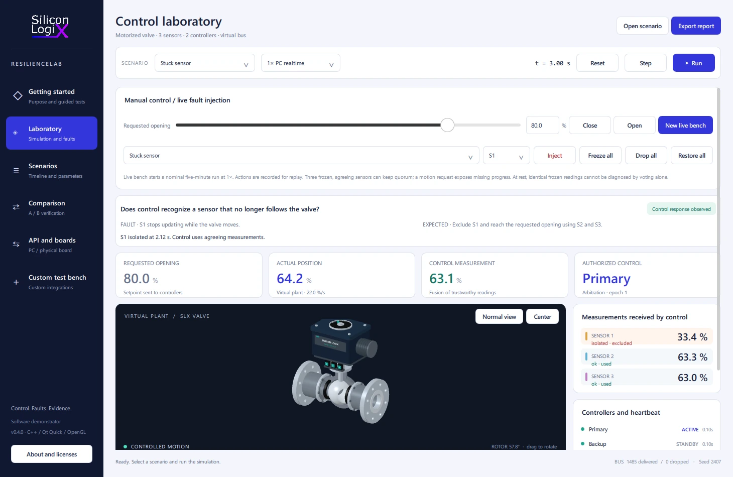
Sensor redundancy compares readings using configurable disagreement thresholds, confirmation times and freshness limits. With two trustworthy measurements, it can exclude a disagreeing sensor; when information is insufficient, it requests a stop. Arbitration authorizes only one controller to command the motor at a time, including during transfer to backup.
Three tests with observable responses
The demonstrator includes three ready-to-run scenarios. The following chart uses traces produced by executing version 0.4.0, with an 80% requested opening, 12 simulated seconds, a 20 ms step and seed 2407. It represents software model results under these stated conditions.
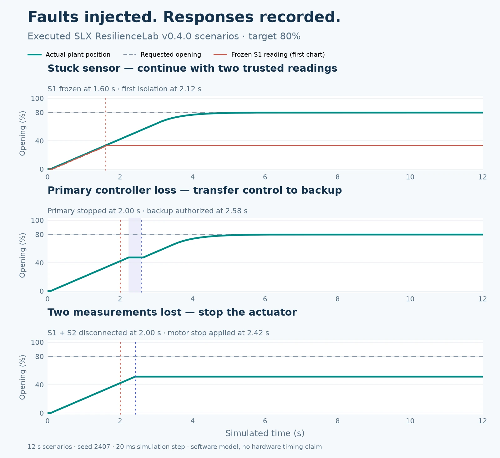
- Stuck sensor. S1 freezes at 1.60 s. The first isolation event appears at 2.12 s, after 0.52 s; the primary isolates S1 at 2.14 s. Control continues with S2 and S3 and finishes with approximately 0.14 percentage points of position error.
- Primary controller loss. The controller stops at 2.00 s. The watchdog stops the motor at 2.24 s and arbitration authorizes backup at 2.58 s: takeover occurs after 0.58 s. The valve resumes movement and finishes with approximately 0.16 percentage points of position error.
- Measurement loss. S1 and S2 disconnect at 2.00 s. Their readings expire at 2.40 s and the motor stop is applied at 2.42 s. Final position is 51.48%: the expected outcome is to stop because sufficient information is unavailable.
The report retains position errors, detections, transfers to backup and stops. HTML, JSON and CSV exports make the evidence accessible and usable in other tools. Configuration, the fault timeline and seed let you replay a scenario and compare two control versions under the same simulated conditions.
Why this approach helps embedded development
The principle is software-in-the-loop: execute compiled code on a computer and subject it to repeatable test inputs. MathWorks' SIL and PIL documentation describes how these environments help verify code behaviour during development. ResilienceLab applies this principle using its own C++ and Qt Quick architecture.
Fault injection makes the condition under test explicit. Alongside the ready-to-run scenarios, the laboratory supports progressive sensor drift, disconnections, intermittent communication and actuator jamming. In a physical bench, electrical faults require dedicated interfaces: NI's explanation of fault insertion units illustrates that testing layer. In this demonstrator, faults affect the model and its messages.
For a development project, the benefit is defining verification criteria early: how many measurements are needed to continue, how quickly a loss should be detected, which controller may issue commands and which events must be retained. The same test can then become a regression check when firmware changes.
From PC control to a board connection
The laboratory also supports live operation: change the requested opening and freeze, disconnect or restore sensors while the valve is moving. Actions are recorded so the test can be reconstructed. 1× mode follows the PC clock; a desktop operating system does not guarantee strict execution deadlines.
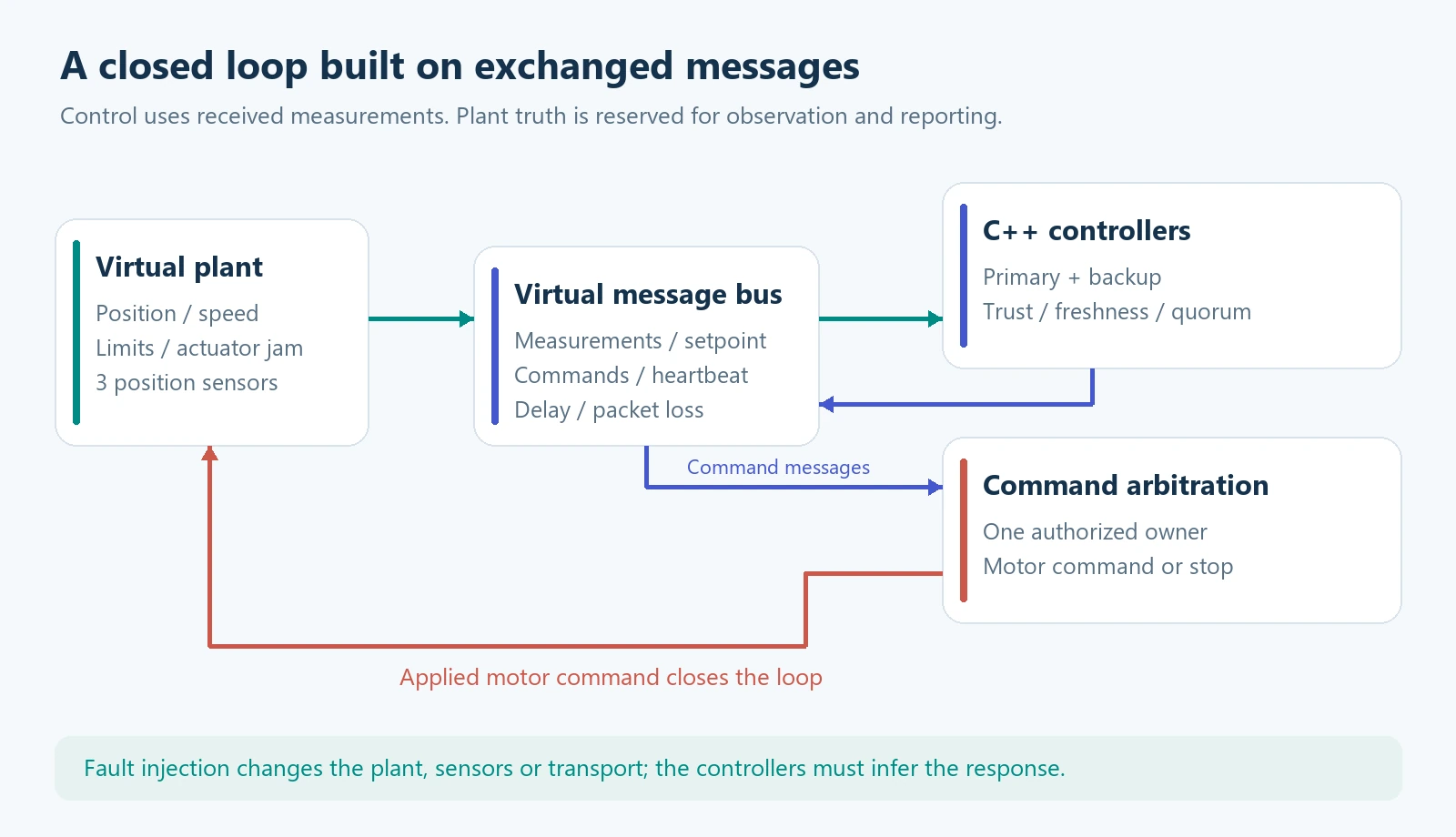
To integrate customer code, a DLL interface with a C API can replace the motor-command calculation on the PC. The bench retains measurement handling, heartbeats and arbitration. A local JSON-message API provides measurements and diagnostics, changes the setpoint and requests faults; local TCP and USB/serial connections are available in the software. Integrating a specific board requires implementing and verifying the corresponding firmware protocol.
A further step is hardware-in-the-loop, connecting a physical controller to a simulated environment. As NI's HIL overview explains, appropriate timing and input/output interfaces are part of that architecture. Board firmware driving the virtual plant is an integration to be developed; ResilienceLab currently provides the software demonstrator and its connection points.
Three sensors frozen at the same value can still agree. Majority voting alone does not establish that the valve is moving: in the laboratory, a movement request also enables measured-progress monitoring. This illustrates why a bench must be designed around the product's faults and requirements. SLX ResilienceLab is a software demonstrator with no safety certification; it does not validate a physical valve or a customer's firmware.
A test bench designed for your product
Silicon LogiX can build a dedicated environment for a board or control system: a plant model, an adapter for the product's interfaces, fault scenarios, acceptance criteria and reports. The starting point can be one concrete function, such as verifying the response to a frozen sensor or interrupted communication.
Tell me about your product, available interfaces and the behaviour you need to verify. If you already have a board, include its protocol, signals and timing requirements. We can define a representative first test and the integration path. Let's discuss your test bench.
Explore the project through the portable Windows v0.4.0 release and the GitHub documentation. The proprietary core is distributed as compiled libraries under the Silicon LogiX evaluation licence; the interface and integration examples are separate.